Difference Amplifier Using The Op Amp Solved Problem Faq 2

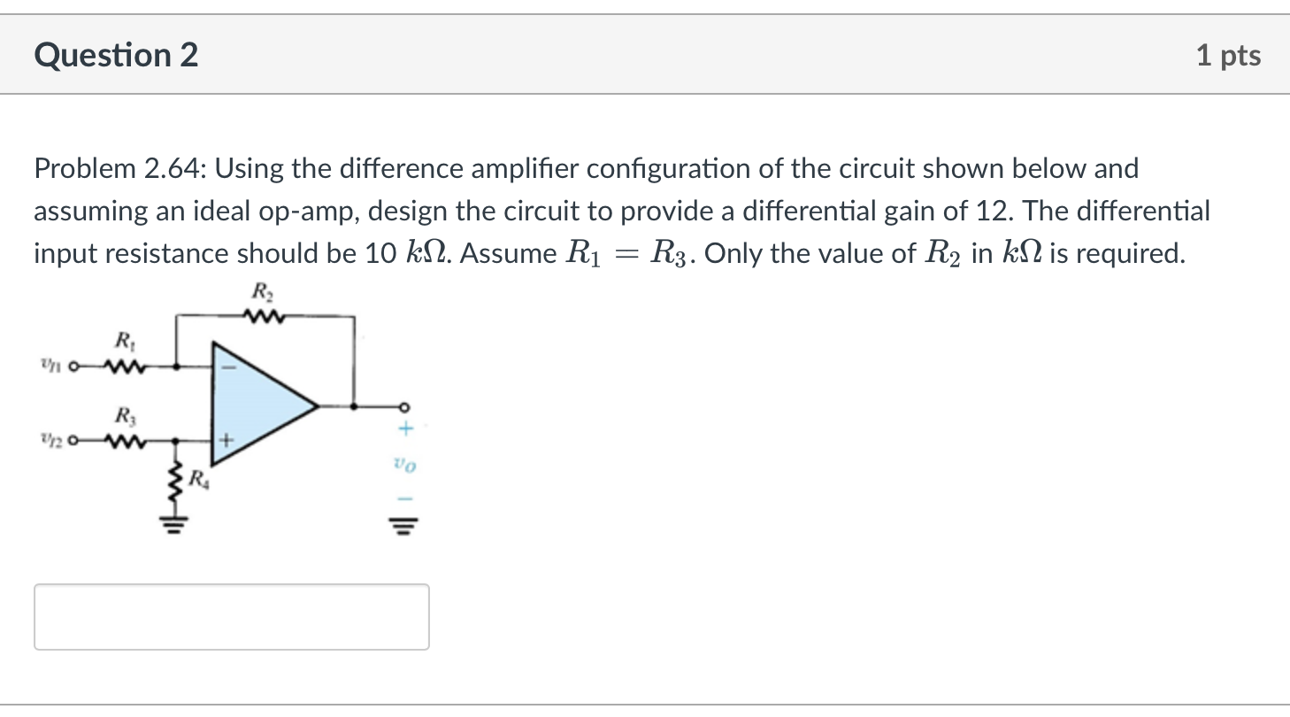
Solved Problem 2 64 Using The Difference Amplifier Chegg In this short video, i am providing the solution to practice problem 3 of the difference amplifier. The gain as well as input resistance of the differential amplifier can be increased by using two op amps. the characteristics of such an amplifier are identical to those of a noninverting amplifier. a practical circuit using differential amplifier with two op amp is given in fig. 34.46.

Jawaban Latihan Soal Op Amp Summing Differensial Amplifier Pdf Pdf The differential amplifier is a voltage subtractor circuit which produces an output voltage proportional to the voltage difference of two input signals applied to the inputs of the inverting and non inverting terminals of an operational amplifier. Difference (or differential) amplifiers are used in various applications where there is a need to amplify the difference between two input signals. they are first cousins of the instrumentation amplifier, the most useful and popular amplifier. Op amps solved problems free download as pdf file (.pdf), text file (.txt) or read online for free. the document contains solutions to 37 problems from chapter 4 on operational amplifiers in irwin's basic engineering circuit analysis textbook. A differential amplifier, also known as difference amplifier, is a very useful op amp configuration that amplifies the difference between the input voltages applied. a differential amplifier is a combination of both inverting and non inverting amplifiers.

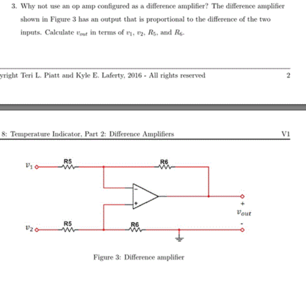
Solved Why Not Use An Op Amp Configured As A Difference Chegg Op amps solved problems free download as pdf file (.pdf), text file (.txt) or read online for free. the document contains solutions to 37 problems from chapter 4 on operational amplifiers in irwin's basic engineering circuit analysis textbook. A differential amplifier, also known as difference amplifier, is a very useful op amp configuration that amplifies the difference between the input voltages applied. a differential amplifier is a combination of both inverting and non inverting amplifiers. In this article i will show how to design a differential amplifier using simple linear algebra. in masteringelectronicsdesign : solving the differential amplifier – part 2, i demonstrate that the same results can be accomplished with the coefficients identification method. Lab 2.3 difference amplifier (see section 2.4, p. 77 of sedra smith) objectives: to study an operational amplifier and a difference amplifier circuit by: completing the analysis of the circuit, and selecting resistors that satisfy design specifications. • simulating the circuit to compare the results with the paper analysis. Connect the channel 1 probe to v1, channel 2 probe to v2, and channel 3 probe to vout on the oscilloscope. the difference amplifier takes the difference of the two input voltages and multiplies it by the gain. Similar to the summer circuit, the subtraction of two input voltages is possible with the help of op amp circuit, called subtractor or difference amplifier circuit. the circuit diagram is shown in the fig. 2.28.1.

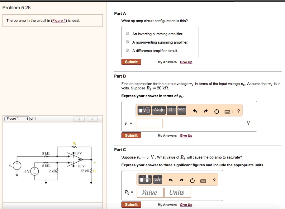
Solved Problem 5 26 Part A The Op Amp In The Circuit In Figure 1 Is Ideal What Op Amp In this article i will show how to design a differential amplifier using simple linear algebra. in masteringelectronicsdesign : solving the differential amplifier – part 2, i demonstrate that the same results can be accomplished with the coefficients identification method. Lab 2.3 difference amplifier (see section 2.4, p. 77 of sedra smith) objectives: to study an operational amplifier and a difference amplifier circuit by: completing the analysis of the circuit, and selecting resistors that satisfy design specifications. • simulating the circuit to compare the results with the paper analysis. Connect the channel 1 probe to v1, channel 2 probe to v2, and channel 3 probe to vout on the oscilloscope. the difference amplifier takes the difference of the two input voltages and multiplies it by the gain. Similar to the summer circuit, the subtraction of two input voltages is possible with the help of op amp circuit, called subtractor or difference amplifier circuit. the circuit diagram is shown in the fig. 2.28.1.

Solved Problem 2 Instrumentation Amplifier Using Dual Op Chegg Connect the channel 1 probe to v1, channel 2 probe to v2, and channel 3 probe to vout on the oscilloscope. the difference amplifier takes the difference of the two input voltages and multiplies it by the gain. Similar to the summer circuit, the subtraction of two input voltages is possible with the help of op amp circuit, called subtractor or difference amplifier circuit. the circuit diagram is shown in the fig. 2.28.1.
Comments are closed.