Diy Ir Remote Control Switch Circuit

Diy Ir Remote Control Switch Circuit Connect whatever you want to the relay, and now you can control that thing with any button on almost any ir remote control! click here to see the circuit on circuit canvas and make your own adjustments >> this project uses a tsop312 ir receiver, a capacitor, and a jk flip flop. In this write up i have explained a couple of these simple infrared remote control circuits designed for controlling any given electrical appliance through an ordinary or tv remote control unit. introduction. controlling household electrical gadgets or any electrical equipment remotely can be fun.

Ir Remote Control Switch Circuit Diagram Circuit Diagram In this tutorial, we are going to make an “ir remote control light switch”. have you ever wanted to turn off the lights without moving, especially when you started a film on tv or when you fell asleep after a busy day?. Commonly used in home automation, lighting control, and fan regulation, it enhances convenience and efficiency with seamless wireless switching. the system consists of an ir receiver module, a signal processing circuit, and a relay to control the connected load. It uses a tsop1738 ir receiver module at the input side to receive the 38 khz frequency ir pulses from the remote control. under normal condition, the output pin of the ir module is at logic high, which means the transistor t1 (bc558 pnp) is cut off and its collector terminal is at logic low. In this circuit, we are using one switch for operating the transmitter, with this we can switch on or off the tv, motor, radio or any other home appliances. we can even control the volume of tv, radio and many more by adding extra circuitry to the actual circuit.

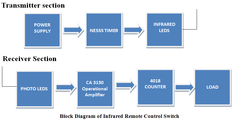
Ir Remote Control Switch Circuit Instructables It uses a tsop1738 ir receiver module at the input side to receive the 38 khz frequency ir pulses from the remote control. under normal condition, the output pin of the ir module is at logic high, which means the transistor t1 (bc558 pnp) is cut off and its collector terminal is at logic low. In this circuit, we are using one switch for operating the transmitter, with this we can switch on or off the tv, motor, radio or any other home appliances. we can even control the volume of tv, radio and many more by adding extra circuitry to the actual circuit. Remote controls, specially cordless type, are very popular nowadays. here is a simple and cost effective cordless remote control circuit which is based on infrared rays. In this post we learn how to build a simple infrared (ir) remote control circuit using tsop1736 ir sensor for controlling home appliances. In the early days, remote controls were used to be huge and complex but now with so many technological advances, you can make it yourself easily with a few components. this circuit will connect any appliances like a light, lamp, or fan and you can switch them on and off. In this project, there are two parts. they are. 1. transmitting section. 2. receiving section. receiving section will be in a stable position which is connected to any load and transmitter will act as a normal remote. here we are showing the block diagram of ir remote control switch.
Comments are closed.