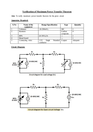
Exp 2 Verification Of Thevenins Theorem And Maximum Power Transfer Theorem Pdf Electrical

Exp 2 Verification Of Thevenins Theorem And Maximum Power Transfer Theorem Pdf Electrical The document describes experiments to verify thevenin's theorem and the maximum power transfer theorem. it provides the theory, circuit diagrams, procedures and sample calculations for each experiment. S experimental verification of kirchhoff’s voltage and current laws experimental verification of network theorem. (thevenin, norton, superposition and maximum power transfer theorem). study of. ro and measurement of sinusoidal voltage, frequency and power factor. expe. ental determination of time constant of series r c electric circu.

Verification Of Maximum Power Transfer Theorem Pdf Voltage Electronic Engineering These graphs demonstrate the validity of the maximum power transfer theorem and the increase of potential difference across the load resistor as the resistance increased. To verify experimentally that the maximum power transferred by a dc source to a load occurs when the resistance of the load equals the resistance of the source. in any electric circuit, the electrical energy from the supply is delivered to the load where it is converted into a useful work. Experiment 5 thÉvenin equivalent circuits and maximum power transfer introduction thévenin’s theorem states that a two terminal circuit may be replaced by an equi. lent two terminal circuit consisting of a voltage source and a series resistance. the thévenin equivalent circuit will deliver the same current and. Maximum power transfer theorem: in a resistive circuit, a resistive load receives maximum power when the load resistance is equal to the thevenin’s equivalent resistance of the circuit (i.e. rl = rth).

Maximum Power Transfer Theorem Proof Formula Experiment 5 thÉvenin equivalent circuits and maximum power transfer introduction thévenin’s theorem states that a two terminal circuit may be replaced by an equi. lent two terminal circuit consisting of a voltage source and a series resistance. the thévenin equivalent circuit will deliver the same current and. Maximum power transfer theorem: in a resistive circuit, a resistive load receives maximum power when the load resistance is equal to the thevenin’s equivalent resistance of the circuit (i.e. rl = rth). By the maximum power transfer theorem, this will be voltage at which maximum power is transferred to the load resistor. carefully remove the potentiometer so as not to accidentally readjust it. The process of finding the load that will receive maximum power from a particular system is quite straightforward due to the maximum power transfer theorem, which states the following:. To verify kirchhoff’s current law and kirchhoff’s voltage law for the given circuit. kcl: the algebraic sum of the currents meeting at a node is equal to zero. kvl: in any closed path mesh, the algebraic sum of all the voltages is zero. voltage control knob should be kept at minimum position. This document describes verifying thevenin's theorem and the maximum power transfer theorem using matlab simulink. it outlines the theory behind both theorems and provides steps to build equivalent circuits in simulink to measure voltages, currents, and power.

Solution 13 Module 1 L7 Thevenins Theorem And Maximum Power Transfer Theorem 28 08 2023 Studypool By the maximum power transfer theorem, this will be voltage at which maximum power is transferred to the load resistor. carefully remove the potentiometer so as not to accidentally readjust it. The process of finding the load that will receive maximum power from a particular system is quite straightforward due to the maximum power transfer theorem, which states the following:. To verify kirchhoff’s current law and kirchhoff’s voltage law for the given circuit. kcl: the algebraic sum of the currents meeting at a node is equal to zero. kvl: in any closed path mesh, the algebraic sum of all the voltages is zero. voltage control knob should be kept at minimum position. This document describes verifying thevenin's theorem and the maximum power transfer theorem using matlab simulink. it outlines the theory behind both theorems and provides steps to build equivalent circuits in simulink to measure voltages, currents, and power.

Verification Of Maximum Power Transfer Theorem Pdf To verify kirchhoff’s current law and kirchhoff’s voltage law for the given circuit. kcl: the algebraic sum of the currents meeting at a node is equal to zero. kvl: in any closed path mesh, the algebraic sum of all the voltages is zero. voltage control knob should be kept at minimum position. This document describes verifying thevenin's theorem and the maximum power transfer theorem using matlab simulink. it outlines the theory behind both theorems and provides steps to build equivalent circuits in simulink to measure voltages, currents, and power.
Comments are closed.