Lab No 8 Verification Of Thevenins Theorem Procedure Of Thevenins Theorem

4 Verification Of Thevenins Theorem Pdf Pdf Electrical Network Voltage Procedure [fig 1: circuit diagram for experimental set up for verification of thevenin's theorem] 1) keep all the resistance close to their maximum respective values. Circuit lab 8 verification of thevenin's theorem@taj . this lecture is from my class lectures in iit ju. .

Verification Of Thevenin S Theorem Solayman Ewu Objective: to verify thevenin's theorem. its provides a mathematical technique for replacing a given network, as viewed from two terminals, by a single voltage source with a series resistance. it makes the solution of complicated networks quite quick and easy. How would you verify thevenin’s theorem in a laboratory setting ? answer: to verify thevenin’s theorem in a lab, we would first determine v th and r th theoretically. then, we’d construct the thevenin equivalent circuit and compare its behavior with the original circuit using various loads. There are 3 steps that must be followed as to complete the theorem calculation, firstly , load resistor must be removed along with the voltage sources which leaves only the resistors. If both the currents are in the same direction then they are additive. if both are in opposite direction the load current is given by, il = higher value of current – lower value of current a. d . he load current will flow in the direction of higher value current) 6. the current il2 is noted with two sources con. ty. (0. er. (w. ns.

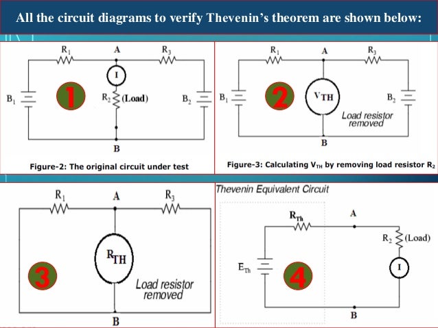
Circuit Lab 8 Verification Of Thevenin S Theorem Taj There are 3 steps that must be followed as to complete the theorem calculation, firstly , load resistor must be removed along with the voltage sources which leaves only the resistors. If both the currents are in the same direction then they are additive. if both are in opposite direction the load current is given by, il = higher value of current – lower value of current a. d . he load current will flow in the direction of higher value current) 6. the current il2 is noted with two sources con. ty. (0. er. (w. ns. The document outlines a procedure for verifying thevenin's theorem through a virtual lab experiment. it includes steps for analyzing thevenin voltage and resistance, as well as determining load current using specified circuit configurations. Determine the value of a load resistor which will allow maximum power transfer to the load. power supply, digital multimeter (dmm), breadboard, resistors, jumper wires. 1. select four resistors: r1 = r2 = r3 = r4 = 2.2 kΩ. measure the values of each of these and record your results in table 1 below. 2. Find vth, rth and the load current il flowing through and load voltage across the load resistor in fig (1) by using thevenin’s theorem. solution: step 1. open the 5kΩ load resistor (fig 2). step 2. calculate measure the open circuit voltage. this is the thevenin voltage (vth). fig (3). 1) the document describes an experiment to verify thevenin's theorem, which states that a linear two terminal circuit can be represented by an equivalent circuit with a voltage source vth and resistor rth. 2) the experiment used a dc power supply, resistors, wires, a voltmeter, and ammeter to construct the circuit and measure voltages and currents.

Verification Of Thevenins Theorem Manufacturers Suppliers And Exporters In India The document outlines a procedure for verifying thevenin's theorem through a virtual lab experiment. it includes steps for analyzing thevenin voltage and resistance, as well as determining load current using specified circuit configurations. Determine the value of a load resistor which will allow maximum power transfer to the load. power supply, digital multimeter (dmm), breadboard, resistors, jumper wires. 1. select four resistors: r1 = r2 = r3 = r4 = 2.2 kΩ. measure the values of each of these and record your results in table 1 below. 2. Find vth, rth and the load current il flowing through and load voltage across the load resistor in fig (1) by using thevenin’s theorem. solution: step 1. open the 5kΩ load resistor (fig 2). step 2. calculate measure the open circuit voltage. this is the thevenin voltage (vth). fig (3). 1) the document describes an experiment to verify thevenin's theorem, which states that a linear two terminal circuit can be represented by an equivalent circuit with a voltage source vth and resistor rth. 2) the experiment used a dc power supply, resistors, wires, a voltmeter, and ammeter to construct the circuit and measure voltages and currents.

Solution Verification Of Thevenins Theorem Experiment Studypool Find vth, rth and the load current il flowing through and load voltage across the load resistor in fig (1) by using thevenin’s theorem. solution: step 1. open the 5kΩ load resistor (fig 2). step 2. calculate measure the open circuit voltage. this is the thevenin voltage (vth). fig (3). 1) the document describes an experiment to verify thevenin's theorem, which states that a linear two terminal circuit can be represented by an equivalent circuit with a voltage source vth and resistor rth. 2) the experiment used a dc power supply, resistors, wires, a voltmeter, and ammeter to construct the circuit and measure voltages and currents.
Comments are closed.