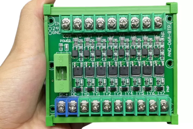
Mosfet %e6%98%af%e4%bb%80%e9%ba%bc Xunying

Bo MẠCh Mosfet 8 Kãªnh 6a A higher vgs, in turn, allows greater conduction until a new equilibrium is reached. this is how the voltage is regulated. a reduction in current drawn will cause this process to happen in reverse. it is worth mentioning this circuit is the mosfet version of the bipolar "emitter follower" topology. 3 i want to make a mosfet model having the following parameters in ltspice: μncox = 100μa v2;vth = 0.5v, λ = 0 μ n c o x = 100 μ a v 2; v t h = 0.5 v, λ = 0 and to define w and l, where i can change it from one design to another.

E6 98 Af E4 Bd A0 E4 Bb Ac E7 9a 84 E8 Af 9d Ef Bc 8c E4 Bd A0 E4 Bb Ac E4 Bc 9a E6 80 8e E4 B9 The intrinsic body diode is the p n junction between the body and the drain. in a discrete (standalone) mosfet, the source and body are usually tied together for convenience to make a three pin package. this means there's a diode between the source and drain: if the source voltage is always lower than the drain voltage, the diode stays off, and everything works as expected. this means you can. Questions: 1) how to calculate the mosfet input resistor? 2) what are the factors affecting the mosfet input resistor calculation? 3) what will be the maximum, minimum resistor value possible and effect in the circuit if the resistor value is changed (increased or decreased) ? please let me know if any further info is required. I am trying to understand the curves of a mosfet. sorry if the question is very basic. where the red point is is the saturation zone of the mosfet, therefore the source drain voltage must be 0v bec. This question is about enhanced n type mosfets. from what i understand, an inversion layer is formed underneath the insulating layer below the gate of the mosfet when a voltage is applied to the ga.

E2 98 Ba Ef B8 8f E2 9d A4 Ef B8 8f F0 9f Aa 84 Follow F0 9f 91 87 F0 9f 91 89 40heart I am trying to understand the curves of a mosfet. sorry if the question is very basic. where the red point is is the saturation zone of the mosfet, therefore the source drain voltage must be 0v bec. This question is about enhanced n type mosfets. from what i understand, an inversion layer is formed underneath the insulating layer below the gate of the mosfet when a voltage is applied to the ga. I am trying to understand this formula to find the transconductance of a mosfet transistor, but i am not getting the passage from the second to the third line. what happened there? thank you. I usually cheat and directly edit c:\program files\ltc\ltspice\lib\sym\standard.mos and add one more line with the .model statement. you need to add mfg= and vpk= manually. I am looking at the following capacitance characteristics of the n mos fds6680a (spice model): how do i understand this graph regarding the conditions? let's take ciss for example. from what i. The mosfet acts like a voltage controlled resistor. this region is used for switching. saturation (vgs > vt and vds > vgs vt) current flows from drain to source. the amount of current is proportional to the square of vgs, and is (almost) independent of vds. the mosfet acts like a voltage controlled current source.

E2 98 Ba Ef B8 8f E2 9d A4 Ef B8 8f F0 9f Aa 84 Follow F0 9f 91 87 F0 9f 91 89 40heart I am trying to understand this formula to find the transconductance of a mosfet transistor, but i am not getting the passage from the second to the third line. what happened there? thank you. I usually cheat and directly edit c:\program files\ltc\ltspice\lib\sym\standard.mos and add one more line with the .model statement. you need to add mfg= and vpk= manually. I am looking at the following capacitance characteristics of the n mos fds6680a (spice model): how do i understand this graph regarding the conditions? let's take ciss for example. from what i. The mosfet acts like a voltage controlled resistor. this region is used for switching. saturation (vgs > vt and vds > vgs vt) current flows from drain to source. the amount of current is proportional to the square of vgs, and is (almost) independent of vds. the mosfet acts like a voltage controlled current source.

A98 B9562 F6 E4 4 B18 89 Bb D2 Ec6 Cf06836 Hosted At Imgbb Imgbb I am looking at the following capacitance characteristics of the n mos fds6680a (spice model): how do i understand this graph regarding the conditions? let's take ciss for example. from what i. The mosfet acts like a voltage controlled resistor. this region is used for switching. saturation (vgs > vt and vds > vgs vt) current flows from drain to source. the amount of current is proportional to the square of vgs, and is (almost) independent of vds. the mosfet acts like a voltage controlled current source.
Comments are closed.