Op Amp Circuit Example 7

Op Amp Circuit Pdf From chapter 7.6 op amp transimpedance amplifier: a transimpedance amplifier (tia) converts a current to a voltage and is often used with current based sensors like photodiodes. it’s also a common building block that helps explain the performance and stability limits of many other op amp circuits. (english) example 7.14 || practice 7.14 || fundamentals of electric circuits alexander & sadikuin this video, we explore example & practice 7.14, focusing o.

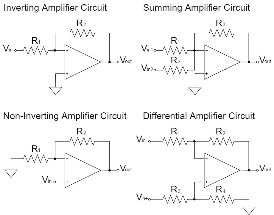
Simple Op Amp Circuit Examples Circuit Diagram The circuit operates from a dual supply vcc and vee which ensures a constant supply. the voltage that appears at the output, vout of the amplifier is the difference between the two input signals as the two base inputs are in anti phase with each other. so as the forward bias of transistor, tr1 is increased, the forward bias of transistor tr2 is reduced and vice versa. An op amp has two inputs, an inverting terminal (labeled „ ”) and a non inverting terminal (labeled „ ”). and has a single output. the first input is called inverting because the output voltage is inverse of the voltage applied at the inverting input, times the gain of the amplifier circuit.if we apply the signal to the non inverting input we get the same signal on the output, times gain. Operational amplifiers (op amp) are linear devices that have all the properties required for nearly ideal dc amplification and are therefore used extensively in signal conditioning or filtering or to perform mathematical operations such as adding, subtracting, integration, and differentiation. the purpose of this article is to present 10 basics circuits for newcomers to electronics designs and. Practice deriving your circuit equations on three operational amplifier(op amp) circuit configuration examples. learn through hands on op amp practice problems, the golden rules and get a more intuitive feel for how op amps work mathematically. toggle nav. tutorials. all tutorials 250 video tutorials.

Solved 7 The Op Amp In The Circuit Below Is Ideal A What Chegg Operational amplifiers (op amp) are linear devices that have all the properties required for nearly ideal dc amplification and are therefore used extensively in signal conditioning or filtering or to perform mathematical operations such as adding, subtracting, integration, and differentiation. the purpose of this article is to present 10 basics circuits for newcomers to electronics designs and. Practice deriving your circuit equations on three operational amplifier(op amp) circuit configuration examples. learn through hands on op amp practice problems, the golden rules and get a more intuitive feel for how op amps work mathematically. toggle nav. tutorials. all tutorials 250 video tutorials. The op amp forces its positive and negative inputs to be equal; hence, the voltage at the negative input of the op amp is equal to vin. the current through the load resistor, rl, the transistor and r is consequently equal to vin r. we put a transistor at the output of the op amp since the transistor is a high current gain stage (often a typical. Op amp fundamentals the operational amplifier : •op amp is a voltage amplifier with extremely high gain (741, gain: 200,000 (v v), op 77, gain: 12 (v uv ) • r d, a, r o are open loop parameters • v p: non inverting v n: inverting • v 0 = a. v d = a (v p –v n) the ideal op amp: •the virtual input short does not draw any current. The addition of the unity gain buffer means that the current into the op amp is zero, so the dac resistor network “sees” the op amp as an infinite resistance, or open circuit. the voltage at the op amp non inverting input, though, is replicated by the op amp output, which can provide that voltage no matter what load r. l. is connected. First add a rload resistor of 470Ω, then 1 kΩ and 4.7kΩ, to the op amp circuit and measure the new output voltage for each value of rload resistor. make sure to record your measurements in the appropriate place on the results sheet. note: the specified output resistance of the ua741 op amp can be found on the ua741 datasheet on page 6 as r o.

Op Amp Circuit Examples Spiceman The op amp forces its positive and negative inputs to be equal; hence, the voltage at the negative input of the op amp is equal to vin. the current through the load resistor, rl, the transistor and r is consequently equal to vin r. we put a transistor at the output of the op amp since the transistor is a high current gain stage (often a typical. Op amp fundamentals the operational amplifier : •op amp is a voltage amplifier with extremely high gain (741, gain: 200,000 (v v), op 77, gain: 12 (v uv ) • r d, a, r o are open loop parameters • v p: non inverting v n: inverting • v 0 = a. v d = a (v p –v n) the ideal op amp: •the virtual input short does not draw any current. The addition of the unity gain buffer means that the current into the op amp is zero, so the dac resistor network “sees” the op amp as an infinite resistance, or open circuit. the voltage at the op amp non inverting input, though, is replicated by the op amp output, which can provide that voltage no matter what load r. l. is connected. First add a rload resistor of 470Ω, then 1 kΩ and 4.7kΩ, to the op amp circuit and measure the new output voltage for each value of rload resistor. make sure to record your measurements in the appropriate place on the results sheet. note: the specified output resistance of the ua741 op amp can be found on the ua741 datasheet on page 6 as r o.
Comments are closed.