Solved 59 A For The Circuit Shown In Figure P5 59 Design Chegg

Solved 59 A For The Circuit Shown In Figure P5 59 Design Chegg Question: 59 (a) for the circuit shown in figure p5.59, design a bias stable circuit such that icq=0.8 ma and vceq=5 v. let β=100. (b) using the results of part (a), determine the percentage change in icq if β is in the range 75≤β≤150. (a) for the circuit shown in figure p5.59, design a bias stable circuit such that i cq = 0.8 ma and v ceq = 5 v. let β = 100. let β = 100. (b) using the results of part (a), determine the percentage change in i c q if β is in the range 75 ≤ β ≤ 150.

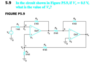
Solved In The Circuit Shown In Figure P5 9 If V What Is Chegg (a) for the circuit shown in figure p5.59, design a bias stable circuit such that i cq = 0.8 ma and v ceq = 5 v. let β = 100. (b) using the results of part (a), determine the percentage change in i cq if β is in the range 75 ≤ β ≤ 150. (c) repeat parts (a) and (b) if r e = 1 k Ω. For the time segment between t= 0 andt = 2 s, the slope of the input signal is (12 2) = 6 v s. the output voltage is given by υout = −rc dυ i dt = −0.1×6= −0.6 v. hence,υout is a square wave with an amplitude of 0.6 v, as shown in the figure. all rights reserved. Find ia by simplifying the circuit (using source transformations) to a single loop circuit so that you need to write only one k vl equation to 10 v 120 find ia. solution: finally, apply kvl: lov 10 v lov 10',' . The circuit shown in figure p 5.2 1b was obtained by simplifying the part to the right of the terminals using source transformations. the part of the circuit to the left of the terminals was not changed.

Solved Exercise 5 9 Consider The Circuit Shown In Figure Chegg Find ia by simplifying the circuit (using source transformations) to a single loop circuit so that you need to write only one k vl equation to 10 v 120 find ia. solution: finally, apply kvl: lov 10 v lov 10',' . The circuit shown in figure p 5.2 1b was obtained by simplifying the part to the right of the terminals using source transformations. the part of the circuit to the left of the terminals was not changed. Di 12 v . t(s) 0 2 4 6 8 10 12 12 v (a) waveform of vit) 50 ΚΩ 2uf di vout vce = 6 v (b) op amp circuit figure p5.59: waveform and circuit for problem 5.59. your solution’s ready to go! our expert help has broken down your problem into an easy to learn solution you can count on. Solutions manual for electrical circuits textbook. college level problems and answers for learning and assessment. (a) for the circuit shown in figure p5.59, design a bias stable circuit such that $i {c q}=0.8 \mathrm{~ma}$ and $v {c e q}=5 \mathrm{~v}$. let $\beta=100$. (b) using the results of part (a), determine the percentage change in $i {c q}$ if $\beta$ is in the range $75 \leq \beta \leq 150$. Question: 5.9 the circuit shown in fig. p5.9 is a generalization of that given in fig. 4.10. we wish to use it to study the lowpass notch and highpass notch filters and also the gain equalizer filter .

Solved Figure 5 Circuit 5figure 5 Circuit 5 First Chegg Di 12 v . t(s) 0 2 4 6 8 10 12 12 v (a) waveform of vit) 50 ΚΩ 2uf di vout vce = 6 v (b) op amp circuit figure p5.59: waveform and circuit for problem 5.59. your solution’s ready to go! our expert help has broken down your problem into an easy to learn solution you can count on. Solutions manual for electrical circuits textbook. college level problems and answers for learning and assessment. (a) for the circuit shown in figure p5.59, design a bias stable circuit such that $i {c q}=0.8 \mathrm{~ma}$ and $v {c e q}=5 \mathrm{~v}$. let $\beta=100$. (b) using the results of part (a), determine the percentage change in $i {c q}$ if $\beta$ is in the range $75 \leq \beta \leq 150$. Question: 5.9 the circuit shown in fig. p5.9 is a generalization of that given in fig. 4.10. we wish to use it to study the lowpass notch and highpass notch filters and also the gain equalizer filter .

Solved Exercise 5 9 Consider The Circuit Shown In Figure Chegg (a) for the circuit shown in figure p5.59, design a bias stable circuit such that $i {c q}=0.8 \mathrm{~ma}$ and $v {c e q}=5 \mathrm{~v}$. let $\beta=100$. (b) using the results of part (a), determine the percentage change in $i {c q}$ if $\beta$ is in the range $75 \leq \beta \leq 150$. Question: 5.9 the circuit shown in fig. p5.9 is a generalization of that given in fig. 4.10. we wish to use it to study the lowpass notch and highpass notch filters and also the gain equalizer filter .
Comments are closed.