Solved Consider The Circuit Shown In Figure 1 A Use The Chegg

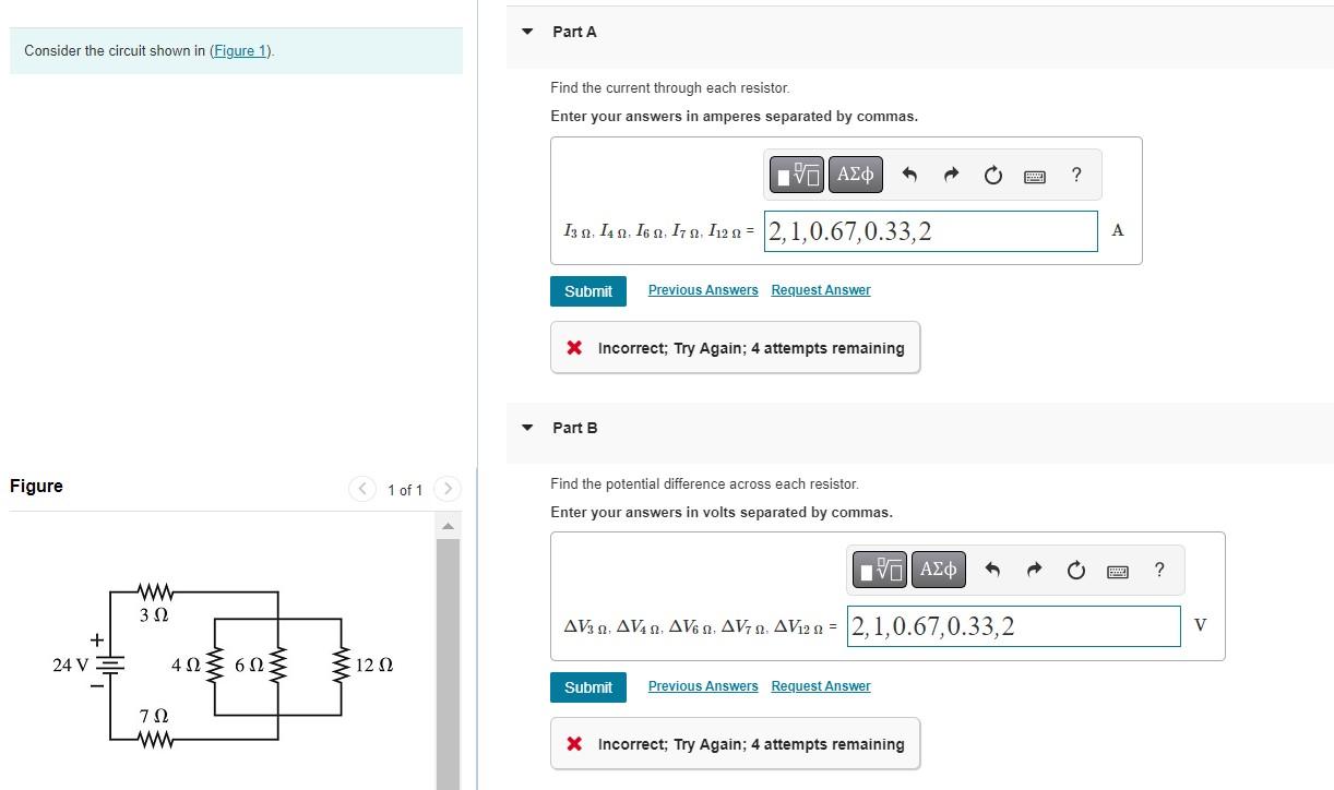
Solved Consider The Circuit Shown In Figure 1 Chegg Question: consider the circuit shown in (figure 1). solve for the value of i1. express your answer to three significant figures and include the appropriate units. To find the current and potential differences across each resistor in the circuit, use ohm's law and consider the arrangement of the resistors. calculate the total resistance to find current through resistor a, then use that to determine voltages across each subsequent resistor.

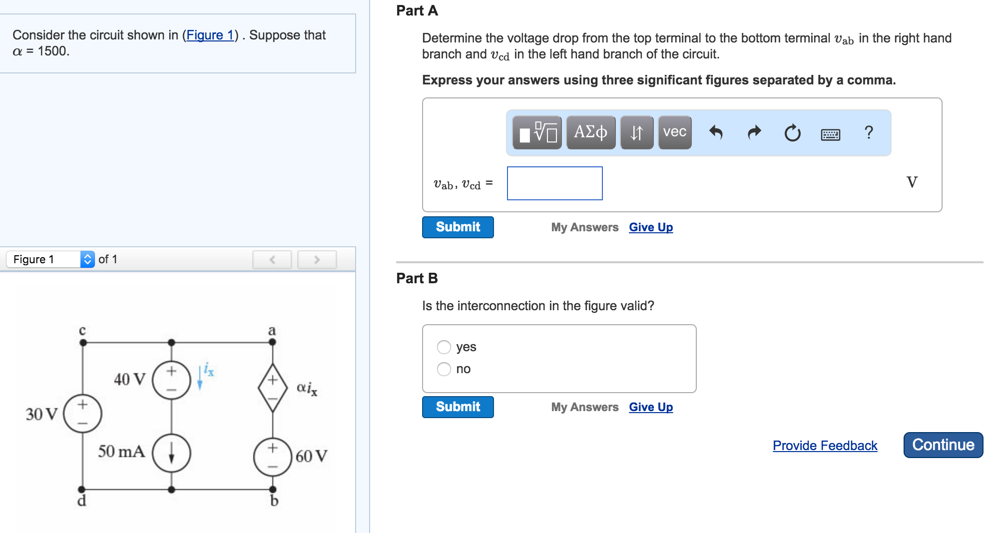
Solved Consider The Circuit Shown In Figure 1 Suppose Chegg Q 1. consider the circuit in fig. 1: (a) find the current i0. consider the circuit in fig. 1: (a) find the current i0. (b) find all the node voltages (c) find the power dissipated. Solution for consider the circuit shown: find i 1. (assuming the circuit includes voltage sources of 12 v and 5 v, and resistors with values r 1=4\,\omega, r 2=3\,\omega, r 3=2\,\omega, the procedure is to assign loop currents, write kvl equations for each loop, and then solve them simultaneously to obtain the desired current i 1. Consider the circuit shown in (figure 1). the diode is the led having the characteristic shown in (figure 2). use graphical load line techniques to solve for i and v for the circuit of (figure 1) jul 25 2025 06:54 pm. expert's answer. solution.pdf help us make our solutions better. rate this solution on a scale of 1 5 star. x. next previous. Video answer: we're supposed to solve this circuit using the node voltage method. so i'm going to call this node v1. this one over here is v2. and we have to put some currents in. we already have i 0. i'm going to add i 1, i 2, and i 3. and.

Solved Consider The Circuit Shown In Figure 1 Figure 1 Of Chegg Consider the circuit shown in (figure 1). the diode is the led having the characteristic shown in (figure 2). use graphical load line techniques to solve for i and v for the circuit of (figure 1) jul 25 2025 06:54 pm. expert's answer. solution.pdf help us make our solutions better. rate this solution on a scale of 1 5 star. x. next previous. Video answer: we're supposed to solve this circuit using the node voltage method. so i'm going to call this node v1. this one over here is v2. and we have to put some currents in. we already have i 0. i'm going to add i 1, i 2, and i 3. and. Step by step guide to drawing the circuit diagram for the circuit shown in figure 1, including clear component placement and connection details. identify and label all components from figure 1. begin by marking the power source as v1, specifying its voltage rating clearly. assign r1, r2, and r3 to the resistors, indicating their resistance. V part d figure < 1 of 1 find the power supplied by the current source. express your answer to three. 10 10 0 submit request answer < return to assignment provide feedback i1=6.4a. i2=6.24a. v= 9.6volts. power=768w. please comment if you have any doubts. i will reply asap. Advanced engineering mathematics 7th edition chegg solutions 5 solutions provide the necessary mathematical framework to understand and model these complex systems. circuit analysis heavily relies on differential equations and linear algebra. signal processing utilizes fourier transforms and laplace transforms to analyze and manipulate signals. There are 2 steps to solve this one. consider the circuit shown in (figure 1). use the mesh current method to find the branch currents ia−if in the circuit. take v=80 v. find ia. express your answer to three significant figures and include the appropriate units.

Solved Consider The Circuit Shown In Figure 1 Figure 1 Of Chegg Step by step guide to drawing the circuit diagram for the circuit shown in figure 1, including clear component placement and connection details. identify and label all components from figure 1. begin by marking the power source as v1, specifying its voltage rating clearly. assign r1, r2, and r3 to the resistors, indicating their resistance. V part d figure < 1 of 1 find the power supplied by the current source. express your answer to three. 10 10 0 submit request answer < return to assignment provide feedback i1=6.4a. i2=6.24a. v= 9.6volts. power=768w. please comment if you have any doubts. i will reply asap. Advanced engineering mathematics 7th edition chegg solutions 5 solutions provide the necessary mathematical framework to understand and model these complex systems. circuit analysis heavily relies on differential equations and linear algebra. signal processing utilizes fourier transforms and laplace transforms to analyze and manipulate signals. There are 2 steps to solve this one. consider the circuit shown in (figure 1). use the mesh current method to find the branch currents ia−if in the circuit. take v=80 v. find ia. express your answer to three significant figures and include the appropriate units.

Solved Consider The Circuit Shown In Figure 1 Figure 1 Of Chegg Advanced engineering mathematics 7th edition chegg solutions 5 solutions provide the necessary mathematical framework to understand and model these complex systems. circuit analysis heavily relies on differential equations and linear algebra. signal processing utilizes fourier transforms and laplace transforms to analyze and manipulate signals. There are 2 steps to solve this one. consider the circuit shown in (figure 1). use the mesh current method to find the branch currents ia−if in the circuit. take v=80 v. find ia. express your answer to three significant figures and include the appropriate units.
Comments are closed.