Solved Fig P4 2 Problem 5 Use Matlab To Find The Transfer Chegg

Question 2 20 Pts Compute The Total Transfer Chegg Fig p4 2 problem 5: use matlab to find the transfer function, g (s) = y (s) r (s) for the following system. find the poles of the system. check the stability of the system. 0 5 x r 8 0 1 5 0 0 0 1 0 x 0 0 0 1 7 9 2 3 y y = [1 3 6 6]x 2. your solution’s ready to go!. Use the figure to find an approximate transfer function for the system. (note: since no further information is given on the system dynamics and due to visual approximations, several solutions are possible.).

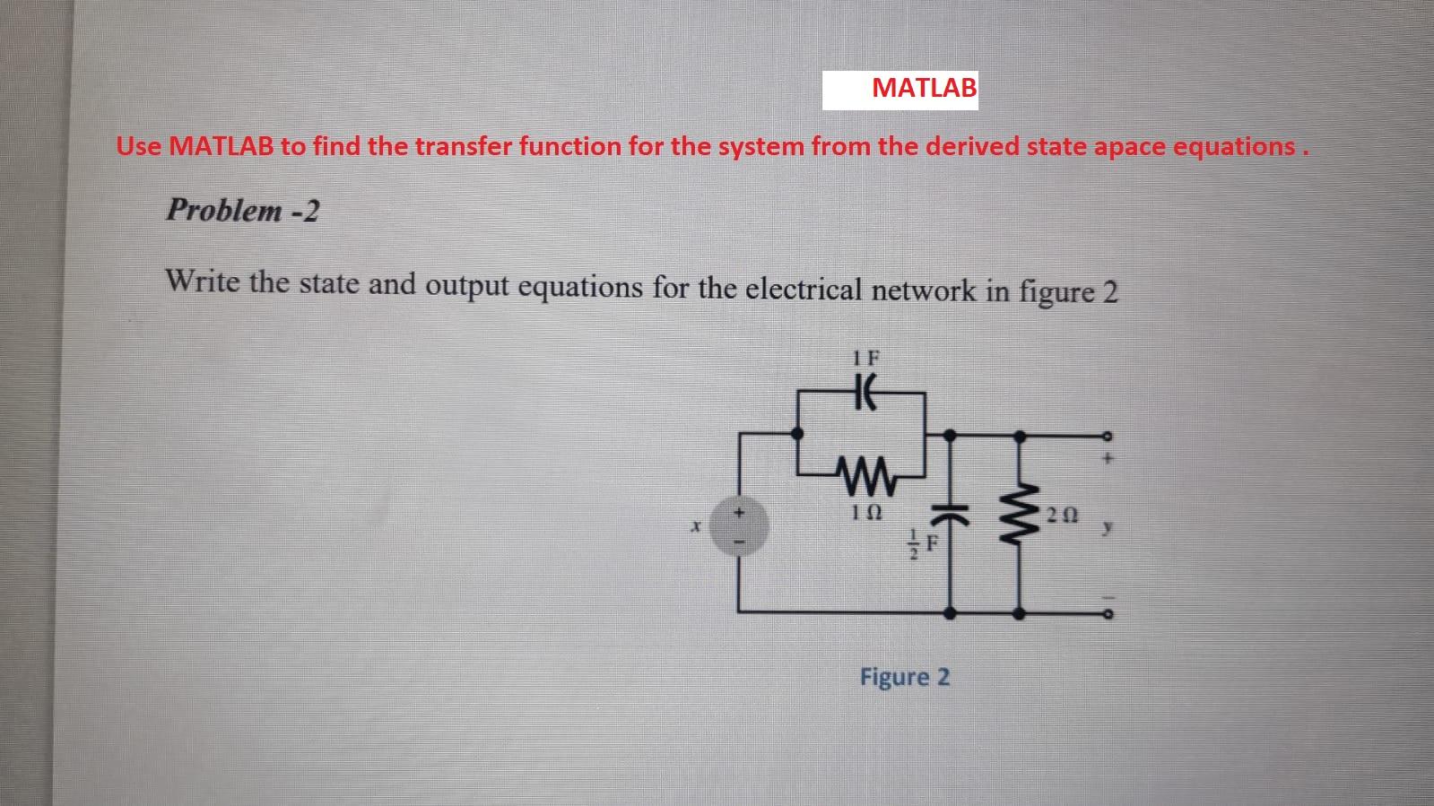
Solved Matlab Use Matlab To Find The Transfer Function For Chegg The problem wants v which is 𝒗=𝒗 −𝒗 = . 𝒎𝑽− . 𝒎𝑽= . 𝒎𝑽 note: this calculation also done in matlab!. Use matlab to plot the output y[n] that is obtained. 4. use convolution and the unit sample response obtained in problem 2 to obtain the output y[n] of the system when the input to the system is a unit step. compare the answer to that obtained in problem 3. 5. use the conv command in matlab to obtain the output of the system due to a unit step. Note: submissions with incorrect filenames or submitted as multiple images pdfs will be rejected. Figure p4.1 3. plot the step responses for problem 2 using matlab. 4. find the capacitor voltage in the network shown in figure p4.2 if the switch closes att 0. assume zero initial conditions. also find the time constant, rise time, and settling time for the capacitor voltage. [sections: 4.2, 4.3] 5 v t= 0 2 Ω 0.5 f figure p4.2 5. plot the.

Solved Fig P4 2 Problem 5 Use Matlab To Find The Transfer Chegg Note: submissions with incorrect filenames or submitted as multiple images pdfs will be rejected. Figure p4.1 3. plot the step responses for problem 2 using matlab. 4. find the capacitor voltage in the network shown in figure p4.2 if the switch closes att 0. assume zero initial conditions. also find the time constant, rise time, and settling time for the capacitor voltage. [sections: 4.2, 4.3] 5 v t= 0 2 Ω 0.5 f figure p4.2 5. plot the. Find the transfer function and poles of the system the mass to m. [sections: 4.2, 4.3] there are 2 steps to solve this one. 1. derive the output responses for all parts of figure 4.7 . [section: 4.4] 2. find the output response, c(t), for each of the systems shown in figure p4,1. Ak jairath: the transfer function of a system is the ratio of lapalce transforms of the output and input quantities, initial conditions being zero. when a physical system is analysed, a mathematical model is prepared by writing differential equations with the help of various laws. Problem set covering periodicity, signal decomposition, rms, energy, transformations, and system properties in signals and systems. Plot the step response for problem 6 using matlab. from your plots find the tome constant, rise time, and settling time.
Comments are closed.