Solved Figure 1 Circuit For Problem 1 Use Nodal Analysis Chegg

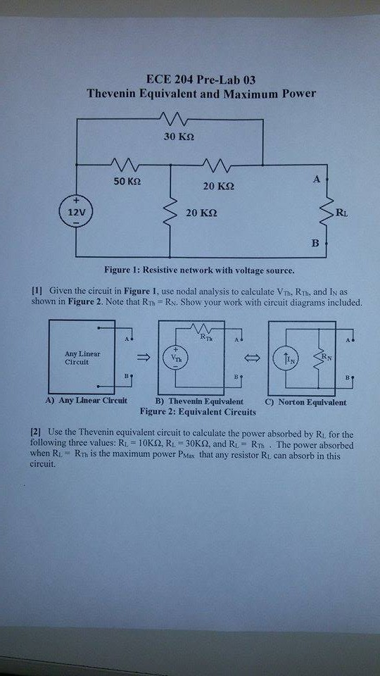
Solved Use Nodal Analysis To Find V1 In The Circuit Below Chegg Solve the circuit of figure 1 using nodal analysis. note that the reference node and the unknown essential node voltages v1 and v2 have already been defined for you, so you should not change the definitions already given in figure 1 above; expect zero credit for not following instructions. Figure 1 circuit diagram for writing nodal equations. equation 2 illustrates the standard format for writing a nodal equation. we can use determinants to solve for the voltages.

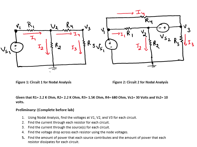
Solved Figure 1 Circuit 1 For Nodal Analysis Figure 2 Chegg In this method, kirchoff's current law is applied at various nodes in an electric circuit. nodal analysis. using nodal analysis determine the current in the 20 Ω resistor. convert all the voltage sources into their equivalent current sources. i1= 10 10 = 1a. i2= 20 10 = 2a. apply kcl to node 1. example: 30. Explore solved problems on nodal analysis. master techniques for analyzing electrical circuits using node voltage method. Figure 3.77. circuit for problem 1 2. use nodal analysis to compute the voltage in the circuit of figure 3.78. answer: figure 3.78. circuit for problem 2 3. use nodal analysis to compute the current through the resistor and the power supplied (or absorbed) by the dependent source shown in figure 3.79. answers: 4. We will end up with one equation per unknown node voltage, and can just solve the system of linear equations to find the branch currents. this example problem features two voltage sources. this.

Solved Given The Circuit In Figure 1 Use Nodal Analysis To Chegg Figure 3.77. circuit for problem 1 2. use nodal analysis to compute the voltage in the circuit of figure 3.78. answer: figure 3.78. circuit for problem 2 3. use nodal analysis to compute the current through the resistor and the power supplied (or absorbed) by the dependent source shown in figure 3.79. answers: 4. We will end up with one equation per unknown node voltage, and can just solve the system of linear equations to find the branch currents. this example problem features two voltage sources. this. For example, the circuit in figure 7.2.9 could be solved using nodal analysis by converting the voltage source and the associated resistance into a current source. that is, \(e r 1\) would be converted into a source \(i 3\) with a parallel resistor \(r 1\). Answer to figure 1: circuit for problem 1. use nodal analysis. Discussion solved problems go 1 11 problem 1 three node circuit solve the circuit shown in fig. 8 by nodal analysis and find the power of i s 1 . − 10v v s1 2Ω r1 2Ω r3 r4 i s1 4Ω 1Ω r2 −2a fig. 8 — problem 1 solution i. identify all nodes in the circuit. There are four nodes in the circuit, as indicated below. ii. select a reference node. let’s choose the bottom node as the reference (ground) node, since all nodes have an equal number of elements connected to them. iii. assign variables for unknown node voltages. we’ll label the remaining three nodes as ( v 1 ), ( v 2 ), and ( v 3 ), as.

Solved Figure 1 Circuit For Problem 1 Solve The Circuit Of Chegg For example, the circuit in figure 7.2.9 could be solved using nodal analysis by converting the voltage source and the associated resistance into a current source. that is, \(e r 1\) would be converted into a source \(i 3\) with a parallel resistor \(r 1\). Answer to figure 1: circuit for problem 1. use nodal analysis. Discussion solved problems go 1 11 problem 1 three node circuit solve the circuit shown in fig. 8 by nodal analysis and find the power of i s 1 . − 10v v s1 2Ω r1 2Ω r3 r4 i s1 4Ω 1Ω r2 −2a fig. 8 — problem 1 solution i. identify all nodes in the circuit. There are four nodes in the circuit, as indicated below. ii. select a reference node. let’s choose the bottom node as the reference (ground) node, since all nodes have an equal number of elements connected to them. iii. assign variables for unknown node voltages. we’ll label the remaining three nodes as ( v 1 ), ( v 2 ), and ( v 3 ), as.
Comments are closed.