Solved Figure 3 Circuit For Problem 3 Problem 3 For The Chegg

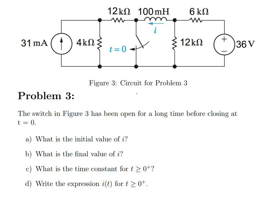
Solved Figure 3 Circuit For Problem 3 Problem 3 The Switch Chegg For the circuit shown in figure 3, determine figure 3 your solution’s ready to go! our expert help has broken down your problem into an easy to learn solution you can count on. Connect the circuit shown in figure 4 4. calculate the total circuit resistance using the following formula: (note: round off the answer to the second decimal place or hundredth of an ohm.) r t 1 = r 1 1 r 2 1 r 3 1.

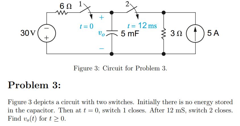
Solved Figure 3 Circuit For Problem 3 Problem 3 Figure 3 Chegg Now, with expert verified solutions from electric circuits 11th edition, you’ll learn how to solve your toughest homework problems. our resource for electric circuits includes answers to chapter exercises, as well as detailed information to walk you through the process step by step. Hint: write the equations to completely solve the circuit, then cross out the ones that aren't needed. further hint: if an unknown appears in but one equation, and that unknown is not needed, the equation (and unknown) can be eliminated. In the circuit below, the switch has been in the closed position for a long time. before the switch is opened, the voltage across the inductor is zero (vl = ldi dt = 0), i.e. the 1 kohm resistor is shorted out by the inductor. Figure 3: circuit for problem 3 problem 3: for the circuit in figure 3, calculate the currents ig and io using circuit simplification and current division. your solution’s ready to go! our expert help has broken down your problem into an easy to learn solution you can count on.

Solved Figure 3 Circuit For Problem 3 Problem 3 Figure 3 Chegg In the circuit below, the switch has been in the closed position for a long time. before the switch is opened, the voltage across the inductor is zero (vl = ldi dt = 0), i.e. the 1 kohm resistor is shorted out by the inductor. Figure 3: circuit for problem 3 problem 3: for the circuit in figure 3, calculate the currents ig and io using circuit simplification and current division. your solution’s ready to go! our expert help has broken down your problem into an easy to learn solution you can count on. Figure 3 : circuit for problem 3 problem 3: the interconnection of ideal sources can lead to an indeterminate solution. with this thought in mind explain why the solutions for v1 and v2 in the circuit in figure 3 are not unique. Draw the small signal equivalent circuit of the amplifier. determine the small signal gain from vi to vout and the input. your solution’s ready to go! our expert help has broken down your problem into an easy to learn solution you can count on. Find v and i in the circuit of fig. 3.11. Each problem solution provides the steps taken to use nodal or loop analysis to solve the circuit, along with the final answers. the document contains solutions to 88 circuit analysis problems from chapter 3 on nodal and loop analysis techniques from the 10th edition of irwin's basic engineering circuit analysis textbook.
Comments are closed.