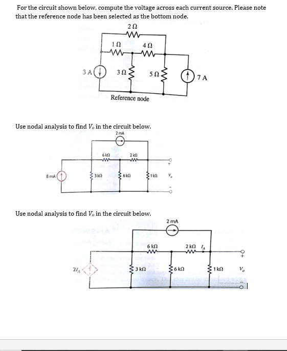
Solved For The Circuit Shown Below Please Compute The Chegg

Solved For The Circuit Shown Below Please Compute The Chegg Question: the circuit is shown as below. please use mesh analysis to calculate voltages v1(t) and v2(t). 1. what is the amplitude of v1(t)? enter your answer in volts without unit. 2. what is the angle of v1(t)? enter your answer in degree without unit. 3. what is. The circuit shown in the figure can be solved using ohm's law and the formula for calculating the total resistance in a series circuit. to find the current (i) flowing through the circuit, we can use the formula i = v r, where v is the voltage and r is the total resistance. in this case, the total resistance (rt) is the sum of r1 and r2: rt.

Solved For The Circuit Shown Below Compute The Voltage Chegg Problem 6.17 for the circuit shown in fig. p6.17 provide the following: (a) an expression for h(ω)=v o v i in standard form. (b) spectral plots for the magnitude and phase of h(ω), given that r =10 Ω,. A) using the superposition theorem, calculate the current i x in the circuit shown below. Example 3: find current 𝑖 in the circuit shown below. solution: the circuit can be redrawn as shown below: 2. loop analysis we looked at kirchhoff's voltage law and applied it for simple circuits containing one loop. loop analysis is a systematic procedure based on kvl to solve for currents in more complex circuits. loop current analysis. So let's start by transforming the circuit we have on the left to a circuit that has all its elements in series. so doing that we can keep our our one and we'll be combining r. two and r. three by using a rule in which we get the equivalent resistance of two elements in parallel.

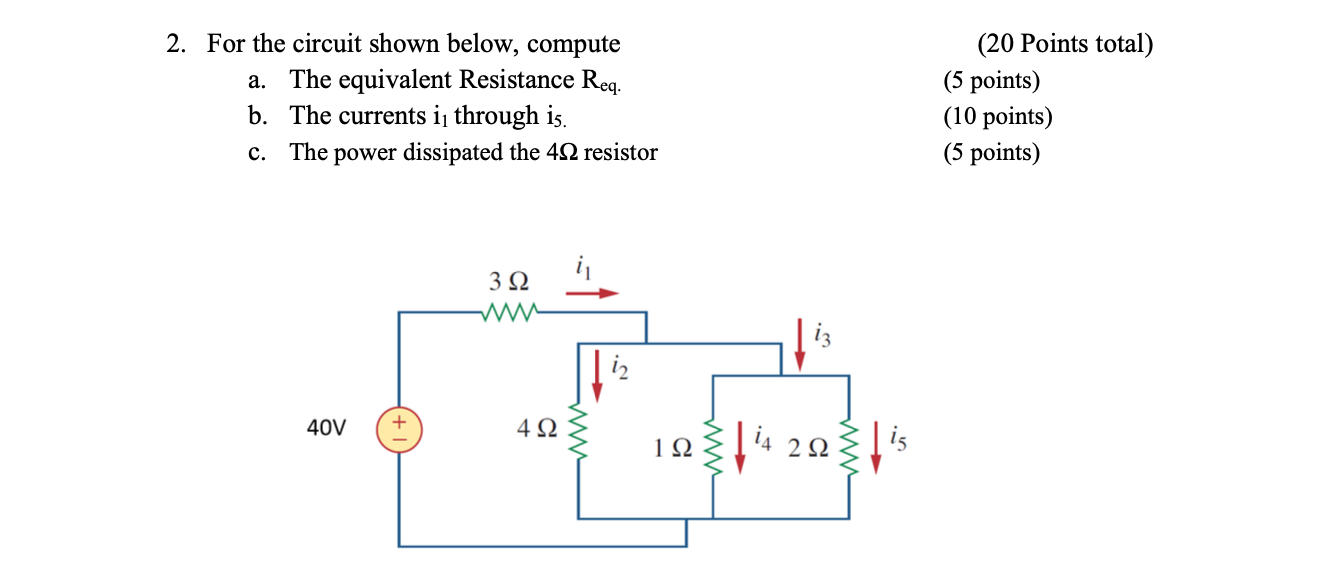
Solved For The Circuit Shown Below Compute The Voltage Chegg Example 3: find current 𝑖 in the circuit shown below. solution: the circuit can be redrawn as shown below: 2. loop analysis we looked at kirchhoff's voltage law and applied it for simple circuits containing one loop. loop analysis is a systematic procedure based on kvl to solve for currents in more complex circuits. loop current analysis. So let's start by transforming the circuit we have on the left to a circuit that has all its elements in series. so doing that we can keep our our one and we'll be combining r. two and r. three by using a rule in which we get the equivalent resistance of two elements in parallel. Consider the circuit shown in figure (a). il(0 ) = 0, and vr(0 ) = 0. but, vr(0 ) vc(0 ) 10 = 0, or vc(0 ) = 10v. (a) at t = 0 , since the inductor current and capacitor voltage cannot change abruptly, the inductor current must still be equal to 0a, the capacitor has a voltage equal to –10v. For the circuit show below find the current and voltage for each of the five resistors. solution. it is a good idea to start by labeling all the currents and voltage as shown below. since all the resistances are known, the first natural step is to find the equivalent resistance. Question: consider the circuit shown in (figure 1). solve for the value of i1. express your answer to three significant figures and include the appropriate units. part b solve for the value of i2. express your answer to three significant figures and include the appropriate units. part c solve for the power for the current source. Here the circuit forms a voltage divider. we can use the voltage divider formula with the impedances. v. o= v. s. z. c. z. c z. r. = (12640 v) j2 . 8 j2. = 2:91635:96 v you should then move the phasor result back to the time domain v.

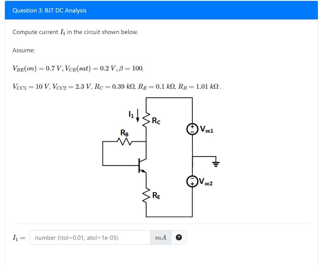
Solved Compute Current I1 In The Circuit Shown Below Chegg Consider the circuit shown in figure (a). il(0 ) = 0, and vr(0 ) = 0. but, vr(0 ) vc(0 ) 10 = 0, or vc(0 ) = 10v. (a) at t = 0 , since the inductor current and capacitor voltage cannot change abruptly, the inductor current must still be equal to 0a, the capacitor has a voltage equal to –10v. For the circuit show below find the current and voltage for each of the five resistors. solution. it is a good idea to start by labeling all the currents and voltage as shown below. since all the resistances are known, the first natural step is to find the equivalent resistance. Question: consider the circuit shown in (figure 1). solve for the value of i1. express your answer to three significant figures and include the appropriate units. part b solve for the value of i2. express your answer to three significant figures and include the appropriate units. part c solve for the power for the current source. Here the circuit forms a voltage divider. we can use the voltage divider formula with the impedances. v. o= v. s. z. c. z. c z. r. = (12640 v) j2 . 8 j2. = 2:91635:96 v you should then move the phasor result back to the time domain v.

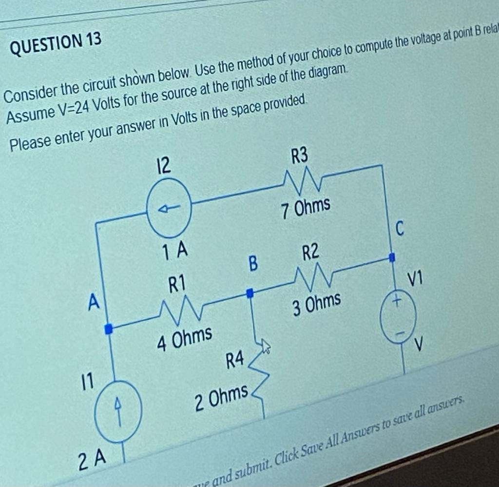
Solved Question 13 Consider The Circuit Shown Below Use The Chegg Question: consider the circuit shown in (figure 1). solve for the value of i1. express your answer to three significant figures and include the appropriate units. part b solve for the value of i2. express your answer to three significant figures and include the appropriate units. part c solve for the power for the current source. Here the circuit forms a voltage divider. we can use the voltage divider formula with the impedances. v. o= v. s. z. c. z. c z. r. = (12640 v) j2 . 8 j2. = 2:91635:96 v you should then move the phasor result back to the time domain v.

Solved 2 For The Circuit Shown Below Compute A The Chegg
Comments are closed.