Solved For The Circuit Shown In Figure 1 Below Determine The Chegg

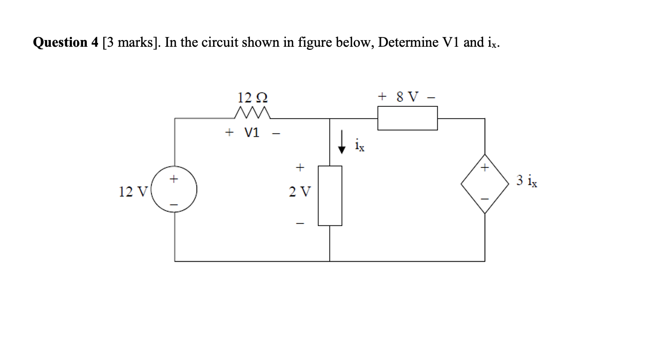
Solved In The Circuit Shown In Figure Below Determine V1 Chegg Consider the circuit shown in figure 1 below, constructed with an ideal opamp. (note: verification of your answers with ltspice, matlab, etc. is not required for this assignment.). Using this information, we can find the value of r3 if we know the total voltage of the circuit by rearranging ohm's law to solve for resistance: r = v i, where v is the potential difference across the particular resistor and i is the current through the circuit.

Solved 1 For The Circuit Shown In Figure Below Determine Chegg The circuit shown in figure p27.17 is connected for 2.00 min. (a) determine the current in studyx 2 a) can the circuit shown in figure be reduced to a single resistor connected to a battery explain calculate the currents (b) 11 (c) 12 and (d) 13 200 240 v 400 300 120 v 100 500 3 for the. Use the mesh current method to find the total power developed in the circuit. use a series of source transformations to find the current io in the circuit. verify your solution by using the node voltage method to find i0. find the norton equivalent with respect to the terminals a, b in the circuit. Consider the circuit shown in (figure 1). the diode is the led having the characteristic shown in (figure 2). use graphical load line techniques to solve for i and v for the circuit of (figure 1) for the circuit shown in fig. 2 (a) determine the transfer function of the circuit (b) determine the response of the system to the input r(t)=e. Assignment #1 solution due date: 09th july 2018 q7. determine the current i d and the diode voltage v d for the circuit shown with v dd = 5 v and r = 1 kΩ. assume that the diode has a current of 1 ma at a voltage of 0.7 v. sol: q8. in each of the ideal diode circuits shown below, v i is a 1 khz, 10 v peak sine wave.

Solved Problem 1 Given The Circuit Shown In Figure 1 Chegg Consider the circuit shown in (figure 1). the diode is the led having the characteristic shown in (figure 2). use graphical load line techniques to solve for i and v for the circuit of (figure 1) for the circuit shown in fig. 2 (a) determine the transfer function of the circuit (b) determine the response of the system to the input r(t)=e. Assignment #1 solution due date: 09th july 2018 q7. determine the current i d and the diode voltage v d for the circuit shown with v dd = 5 v and r = 1 kΩ. assume that the diode has a current of 1 ma at a voltage of 0.7 v. sol: q8. in each of the ideal diode circuits shown below, v i is a 1 khz, 10 v peak sine wave. Consider the circuit shown in (figure 1). solve for the value of i1. express your answer to three significant figures and include the appropriate units. part b solve for the value of i2. express your answer to three significant figures and include the appropriate units. part c solve for the power for the current source. There are 2 steps to solve this one. the transfer function is g not the question you’re looking for? post any question and get expert help quickly. P 3.3 7 determine the value of voltage v in the circuit shown in figure p 3.3 7. do a voltage walk around the circuit, so we can solve for the current in the circuit. starting. Suppose that r1= 12 Ω, r2 = 26 Ω , r3 = 12 Ω , r4 = 34 Ω , r5 = 5 Ω. a. determine the value of v2 by using mesh current analysis. b. determine the power delivered by the source. see explanation section for solution. = ( 5 ) 908 3 801 = 0 5361 v b ) power delivered by source (12 1) " , = 12) 1831 3805 = 5. 7 745 w.

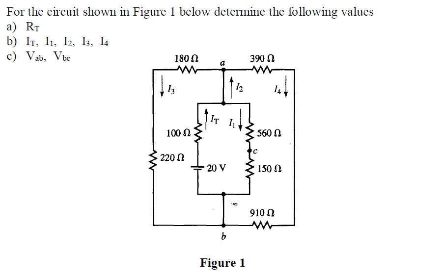
Solved For The Circuit Shown In Figure 1 Below Determine The Chegg Consider the circuit shown in (figure 1). solve for the value of i1. express your answer to three significant figures and include the appropriate units. part b solve for the value of i2. express your answer to three significant figures and include the appropriate units. part c solve for the power for the current source. There are 2 steps to solve this one. the transfer function is g not the question you’re looking for? post any question and get expert help quickly. P 3.3 7 determine the value of voltage v in the circuit shown in figure p 3.3 7. do a voltage walk around the circuit, so we can solve for the current in the circuit. starting. Suppose that r1= 12 Ω, r2 = 26 Ω , r3 = 12 Ω , r4 = 34 Ω , r5 = 5 Ω. a. determine the value of v2 by using mesh current analysis. b. determine the power delivered by the source. see explanation section for solution. = ( 5 ) 908 3 801 = 0 5361 v b ) power delivered by source (12 1) " , = 12) 1831 3805 = 5. 7 745 w.

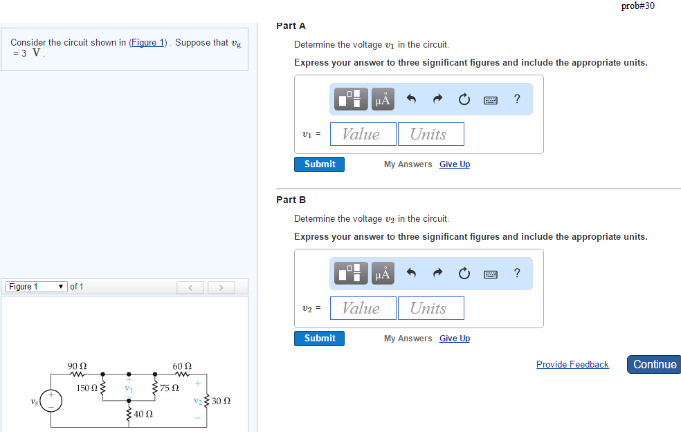
Solved Consider The Circuit Shown In Figure 1 Suppose That Chegg P 3.3 7 determine the value of voltage v in the circuit shown in figure p 3.3 7. do a voltage walk around the circuit, so we can solve for the current in the circuit. starting. Suppose that r1= 12 Ω, r2 = 26 Ω , r3 = 12 Ω , r4 = 34 Ω , r5 = 5 Ω. a. determine the value of v2 by using mesh current analysis. b. determine the power delivered by the source. see explanation section for solution. = ( 5 ) 908 3 801 = 0 5361 v b ) power delivered by source (12 1) " , = 12) 1831 3805 = 5. 7 745 w.
Comments are closed.