Solved Question 1 Consider The Circuit Shown In Figure 1 A Chegg

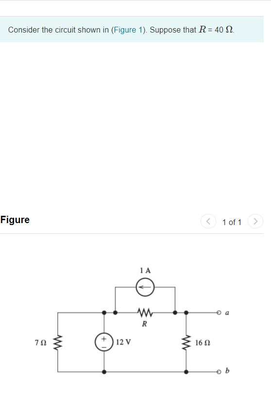
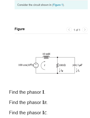
Solved Consider The Circuit Shown In Figure 1 Suppose Chegg There are 2 steps to solve this one. the transfer function is g not the question you’re looking for? post any question and get expert help quickly. To find the current and potential differences across each resistor in the circuit, use ohm's law and consider the arrangement of the resistors. calculate the total resistance to find current through resistor a, then use that to determine voltages across each subsequent resistor.

Solved Consider The Circuit Shown In Figure 1 Suppose Chegg Q help me the pre lab 5 questions on the top, please. 1. design a moore finite state machine to meet the specifications. Chegg homework help questions and answers find equivalent resistance combination resistors shown figure r1 252 r2 221 q70014024 (a) what is the equivalent resistance of five resistors connected in series with a 21.0 v battery if each resistor has a value of 22.0 Ω?. Circuit reduction and ohm's law find v1 and i in the circuit shown using circuit reduction method and ohm's law: manually draw the successive reduction steps and show the calculations. submit a word, pdf, or jpeg image of this completed sheet. Video answer: we're supposed to solve this circuit using the node voltage method. so i'm going to call this node v1. this one over here is v2. and we have to put some currents in. this problem has been solved. by verified expert sam stansfield 100% free to try get full access instantly. start free trial.

Solved Consider The Circuit Shown In Figure 1 Figure 1 Of Chegg Circuit reduction and ohm's law find v1 and i in the circuit shown using circuit reduction method and ohm's law: manually draw the successive reduction steps and show the calculations. submit a word, pdf, or jpeg image of this completed sheet. Video answer: we're supposed to solve this circuit using the node voltage method. so i'm going to call this node v1. this one over here is v2. and we have to put some currents in. this problem has been solved. by verified expert sam stansfield 100% free to try get full access instantly. start free trial. Eels are able to generate current with biological cells called electroplaques. the electroplaques in an eel are arranged in 100 rows, each row stretching horizontally along the bo. There are 3 steps to solve this one. the equation of motion for a damped forced vibration system is deriv not the question you’re looking for? post any question and get expert help quickly. V part d figure < 1 of 1 find the power supplied by the current source. express your answer to three. 10 10 0 submit request answer < return to assignment provide feedback i1=6.4a. i2=6.24a. v= 9.6volts. power=768w. please comment if you have any doubts. i will reply asap. Current to voltage converter is an op amp circuit which accepts an input current and gives an output voltage that is proportional to the input current. the basic current to voltage converter is shown on figure 5.
Comments are closed.