Solved Question 4 For The Timer Circuit Shown The Timer Chegg

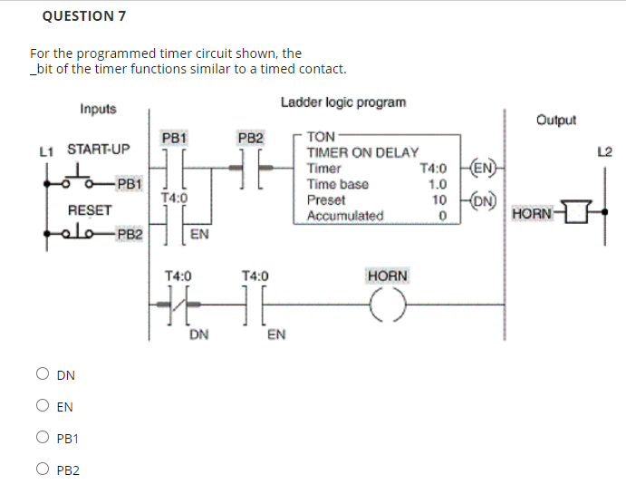
Solved Question 4 For The Timer Circuit Shown The Timer Chegg Our expert help has broken down your problem into an easy to learn solution you can count on. there’s just one step to solve this. input a switch. For the programmed timer circuit shown, assume the switch is closed for 5 seconds and than opened. after 12 seconds have elapsed motor (s) will still be operating.

Solved Question 4 For The Timer Circuit Shown The Timer Chegg Challenge question: write an equation solving for the average current drawn by the 555 timer circuit as it charges and discharges the capacitor while generating a 50% duty cycle pulse. Quiz 4 review free download as pdf file (.pdf), text file (.txt) or read online for free. this document contains a 57 multiple choice question quiz reviewing concepts related to mechanical timing relays and plc timers. Question 1: calculate the time constant (τ) using equation (1) (r= 2.2kohm, c=0.01uf) and compare it to the measured values. repeat this for other set of r and c values (r = 10 kΩ and c = 0.01 µf). answer: the time constant, τ is found using the formula: τ = r x c and the measurement unit of the result will be in seconds. thus, applying the above formula for the given values of r and c. Question: for the timer circuit as shown, assuming no reset rung for t4:1 is true, which output lights will be lit at the end of the current scan cycle?.

Solved Question 7 For The Programmed Timer Circuit Shown Chegg Question 1: calculate the time constant (τ) using equation (1) (r= 2.2kohm, c=0.01uf) and compare it to the measured values. repeat this for other set of r and c values (r = 10 kΩ and c = 0.01 µf). answer: the time constant, τ is found using the formula: τ = r x c and the measurement unit of the result will be in seconds. thus, applying the above formula for the given values of r and c. Question: for the timer circuit as shown, assuming no reset rung for t4:1 is true, which output lights will be lit at the end of the current scan cycle?. Study with quizlet and memorize flashcards containing terms like the on delay timer (ton) starts timing when the timer's:, for the program shown, the timer accumulated time is set to zero anytime: pb1 is closed. pb2 is closed. pb1 is open. At time t=0, the switch was closed. determine: (a) draw the circuit for t< 0 and obtain the current from the inductor i (0). (2 marks) (b) draw the circuit for t> 0 and obtain the current from the inductor. An alarm is to be switched on whenever a piping system has sustained a cumulative overpressure of 60 seconds. the most directly applicable timer to use would be the on delay non retentive timer. Question 4 for the 555 timer oscillator circuit shown in figure 4, calculate the value for r1 and r2 so that the oscillator has a frequency of 2.5 khz @ 60% duty cycle.

Solved Question 7 For The Programmed Timer Circuit Shown Chegg Study with quizlet and memorize flashcards containing terms like the on delay timer (ton) starts timing when the timer's:, for the program shown, the timer accumulated time is set to zero anytime: pb1 is closed. pb2 is closed. pb1 is open. At time t=0, the switch was closed. determine: (a) draw the circuit for t< 0 and obtain the current from the inductor i (0). (2 marks) (b) draw the circuit for t> 0 and obtain the current from the inductor. An alarm is to be switched on whenever a piping system has sustained a cumulative overpressure of 60 seconds. the most directly applicable timer to use would be the on delay non retentive timer. Question 4 for the 555 timer oscillator circuit shown in figure 4, calculate the value for r1 and r2 so that the oscillator has a frequency of 2.5 khz @ 60% duty cycle.
Comments are closed.