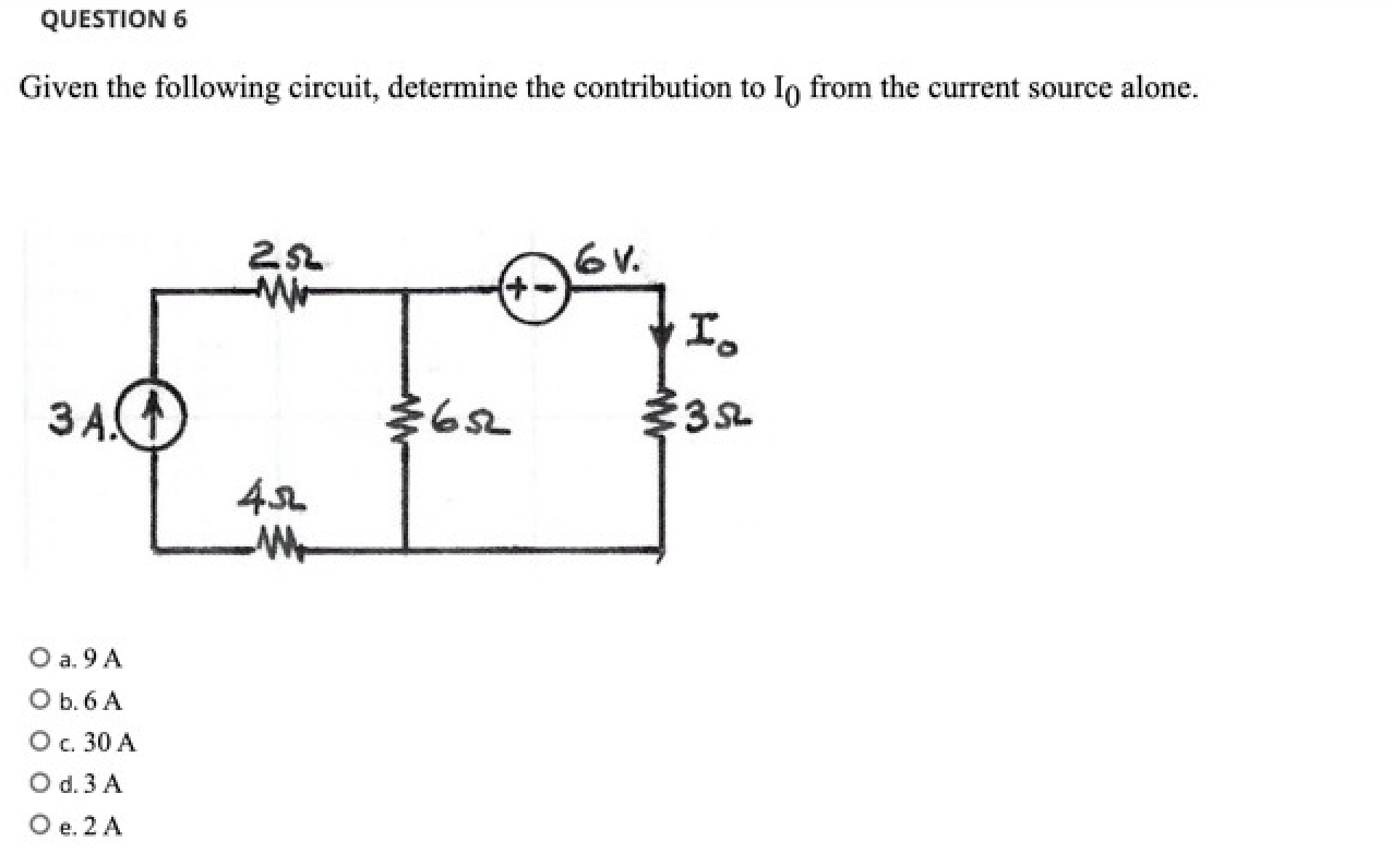
Solved Question 6 Given The Following Circuit Determine The Chegg

Question Chegg For the given circuit, determine i. your solution’s ready to go! our expert help has broken down your problem into an easy to learn solution you can count on. Select the correct statement(s) regarding the ideal op amp differentiator circuit. s1: the output voltage is zero for a constant input voltage. s2: the output voltage is the sum of the input signal.

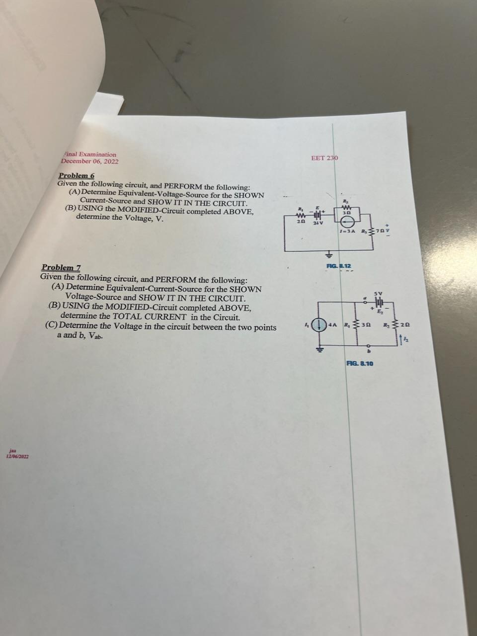
Solved Question 6 Given The Following Circuit Determine The Chegg A 741 op amp shown in the circuit given below has an open loop voltage gain of 70000, an input resistance of 2 mq, and an output resistance of 150 q. calculate the output voltage vo in the op amp circuit. 741 the output voltage of the op amp is 0.999986 ± mv. Q8. in each of the ideal diode circuits shown below, v i is a 1 khz, 10 v peak sine wave. sketch the waveform resulting at vo. what are its positive and negative peak values? 1) 2) 3) 4) sol: q9. find the value of r of the circuit below to provide vo = 2.4 v given that the diode has 0.7 v drop at 1ma. sol:. Here’s the best way to solve it. problem 6 given the following circuit, and perform the following: (a) determine equivalent voltage source for the shown current source and show it in the circuit. [b] determine the voltage across each of the resistors in the following circuit and the power dissipated in each of them. calculate the power supplied by the voltage source.

Solved Problem 6 Given The Following Circuit And Perform Chegg Here’s the best way to solve it. problem 6 given the following circuit, and perform the following: (a) determine equivalent voltage source for the shown current source and show it in the circuit. [b] determine the voltage across each of the resistors in the following circuit and the power dissipated in each of them. calculate the power supplied by the voltage source. 7 determine the currents i1, i2, i3 for the network shown. use practical model for the diodes. In the circuit given below, r = 10 q. the switch in the circuit moves from position a to position b at t= o (please note that the switch must connect to point b before it breaks the connection at a, a make before break switch). Question 6: consider the following second order circuit in figure q6. Thevenin’s theorem states that to get the equivalent resistance between two points, we short circuit the voltage source and open circuit the current source and if we have dependent sources as well, we put a voltage source or a current source at the terminal where the equivalent resistance is to be obtained. calculation: given circuit:.

Solved 8 Given The Following Circuit Do A Determine Chegg 7 determine the currents i1, i2, i3 for the network shown. use practical model for the diodes. In the circuit given below, r = 10 q. the switch in the circuit moves from position a to position b at t= o (please note that the switch must connect to point b before it breaks the connection at a, a make before break switch). Question 6: consider the following second order circuit in figure q6. Thevenin’s theorem states that to get the equivalent resistance between two points, we short circuit the voltage source and open circuit the current source and if we have dependent sources as well, we put a voltage source or a current source at the terminal where the equivalent resistance is to be obtained. calculation: given circuit:.
Comments are closed.