Solved Umf 6 33 A Do The Problem As Stated But Also Find I T B Simulate Using Ltspice C

2 Umf 6 33 A Do The Problem As Stated By Also Find Chegg Question: please solve the following problem by hand using a time domain method (not the laplace method!). simulate the circuit with ltspice to find what il (t) would be. As you already pointed out in your answer, you can now generate as many equations as you like by arbitrarily setting different combinations of values for va v a, vb v b, and vc v c and solve those simultaneously.

Solved 4 Umf P6 32 With Additions A Do The Problem As Chegg Please solve the following problem by hand using a time domain method (not the laplace method!). simulate the circuit with ltspice to find what il (t) would be. To plot the results from (a) and (b) using matlab, we need to first obtain the values of vc (t) from the ltspice simulation. we can then use the plot function in matlab to plot the results obtained from both the analytical solution and the ltspice simulation. U&m 6.3 a) do the problem as stated b) find vc (t) for t≥0. assume l=9µh and c=1pf. laplace solution since we have zero initial condition values the capacitors transform to just 1 ( s c ) term . Figure 6.65 chapter 6, solution 33 because this is a totally capacitive circuit, we can combine all the capacitors using the property that capacitors in parallel can be combined by just adding their values and we combine capacitors in series by adding their reciprocals.

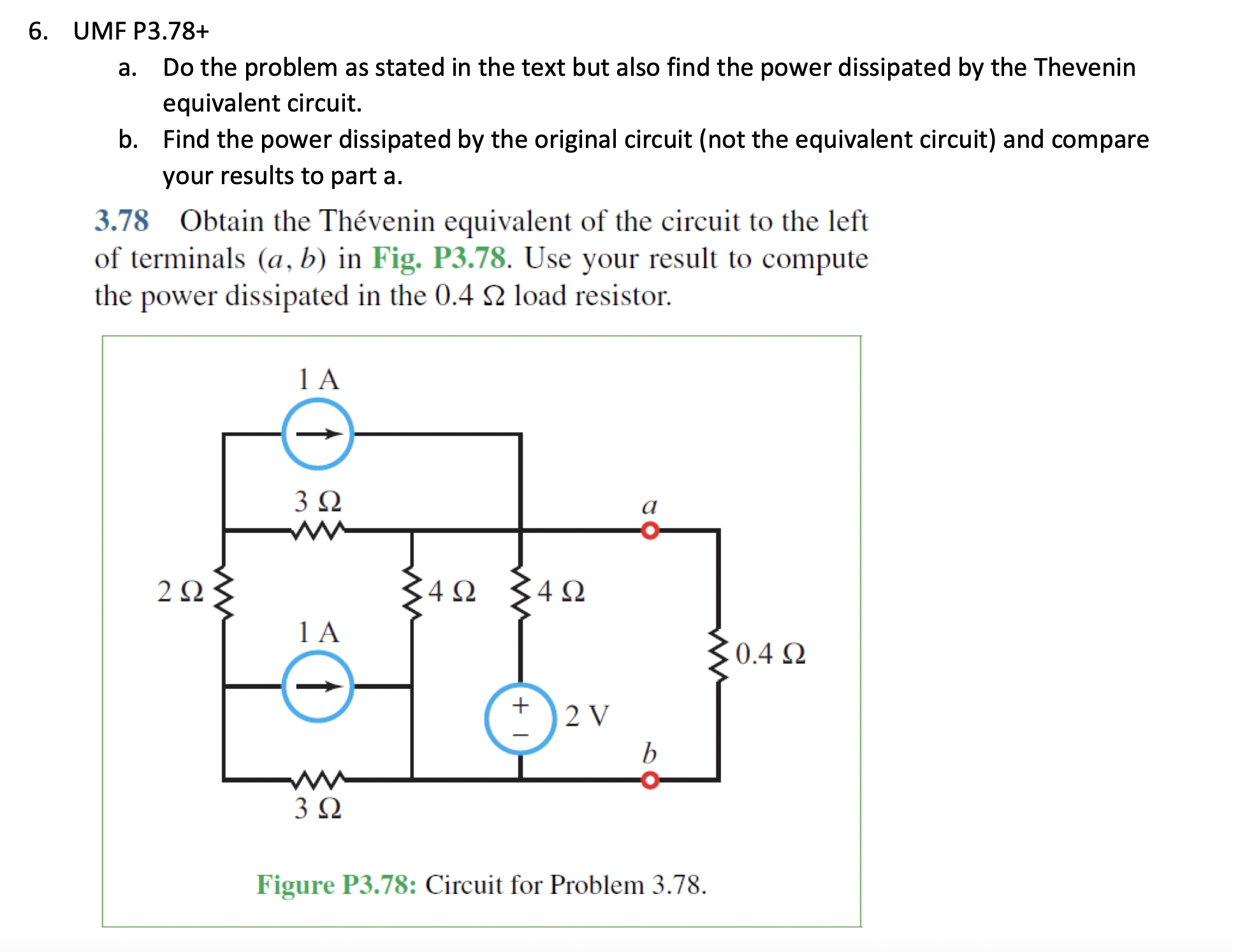
Solved Umf P3 78 A Do The Problem As Stated In The Text Chegg U&m 6.3 a) do the problem as stated b) find vc (t) for t≥0. assume l=9µh and c=1pf. laplace solution since we have zero initial condition values the capacitors transform to just 1 ( s c ) term . Figure 6.65 chapter 6, solution 33 because this is a totally capacitive circuit, we can combine all the capacitors using the property that capacitors in parallel can be combined by just adding their values and we combine capacitors in series by adding their reciprocals. Determine i1 and i2 in the circuit of fig. p2.67. assume vf = 0.7 v for both diodes. for the ideal diode with offset model, there are always two possibilities: either the diode is conducting and has vf dropped across it or it is reverse biased (negative vd) and no current flows through it. Please solve the following problem by hand using a time domain method (not the laplace method!). simulate the circuit with ltspice to find what il (t) would be. A magnetic field b exists in the region in the direction perpendicular to the plane of the rails. the rails are connected at the top end by a capacitor of capacitance c. find the acceleration of the wire neglecting any electric resistance. Solution: transforming the circuit to the phasor domain leads to fig. p7.33 (a). −j25Ω 30Ω 10Ω j10Ω 40e−110˚ v i a i1 i 2 fig. p7.33 (a) vs = 40e− 20 e− 90 =40e− 110 v, 1 jωc= −j 200×200×10−6 = j25Ω, jωl= j200×50×10−3 = j10Ω. mesh analysis gives: −40e− 110 i1(30− j25)−30.

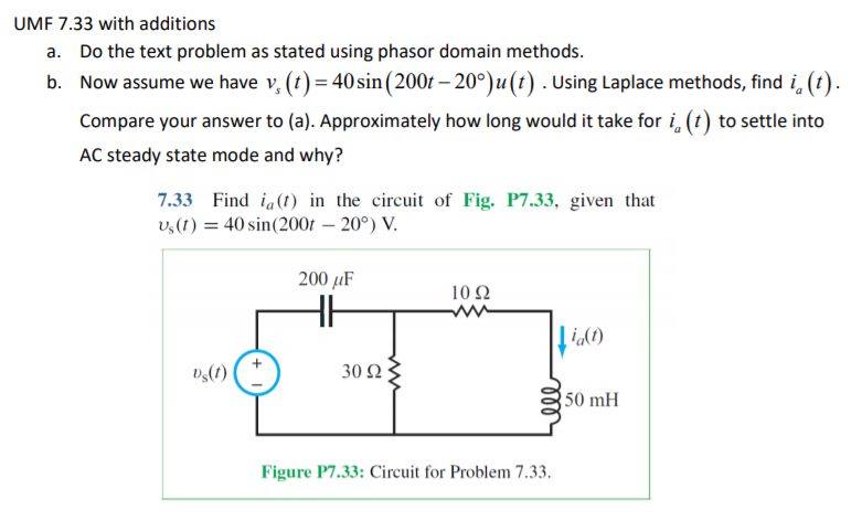
Solved Umf 7 33 With Additions A Do The Text Problem As Chegg Determine i1 and i2 in the circuit of fig. p2.67. assume vf = 0.7 v for both diodes. for the ideal diode with offset model, there are always two possibilities: either the diode is conducting and has vf dropped across it or it is reverse biased (negative vd) and no current flows through it. Please solve the following problem by hand using a time domain method (not the laplace method!). simulate the circuit with ltspice to find what il (t) would be. A magnetic field b exists in the region in the direction perpendicular to the plane of the rails. the rails are connected at the top end by a capacitor of capacitance c. find the acceleration of the wire neglecting any electric resistance. Solution: transforming the circuit to the phasor domain leads to fig. p7.33 (a). −j25Ω 30Ω 10Ω j10Ω 40e−110˚ v i a i1 i 2 fig. p7.33 (a) vs = 40e− 20 e− 90 =40e− 110 v, 1 jωc= −j 200×200×10−6 = j25Ω, jωl= j200×50×10−3 = j10Ω. mesh analysis gives: −40e− 110 i1(30− j25)−30.
Comments are closed.